Recovering a bricked MP Mini Delta 3D Printer

It’s been five years since my last update, so I figured I’d write-up a fun reverse engineering journey I recently had.

For years I’d been putting off getting a 3D printer, mostly because of the cost and the space it would take up on my workbench. So when a friend of mine sent me a link to the MP Mini Delta 3D Printer campaign on Indiegogo, I couldn’t resist buying it. I’d had positive experiences with monoprice printers in the past, so I figured it was worth the risk.

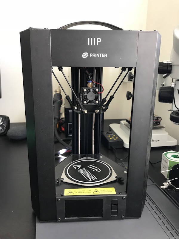
The printer arrived in August 2017 as promised, and best of all, it worked exactly as advertised.

Fast-forward to January 2018. My friend Dave stopped by my place while I was in the middle of a print (cases for my “one-key” keyboard). Needless to say, he was blown away by the price point and ordered one for himself right there on the spot. After it arrived, he decided to try the firmware update using an SD card and the instructions found on the Monoprice Mini Delta wiki page. Based on all the warnings and comments, this update seemed risky, but he had no trouble updating his unit.

Now you may ask: “why update if it’s risky?”. Turns out the old firmware has several serious bugs such as “randomly crash into the printer bed and stall until a power cycle occurs”. To me, this firmware update sounded like a great idea. Especially given the fact that Dave was able to update his unit without any issues. In fact, I figured I’d use his SD card to update my machine, as it seemed less risky. So I inserted the SD card, selected the bin file for the firmware update, and hit go.

(…this is the point in the story where everything turned to shit.)

Needless to say, the firmware update wasn’t successful. And worst of all, the printer was no longer responding.

“What’s the first thing to try?”, I thought. “Try turning it off and on again of course!”

Except every time I did this, the printer would show the boot screen with the “IIIP” logo, but without a firmware version (not a good sign). The main menu would appear, but all the temperature readouts read “0” and the printer no longer enumerating as a USB device.

How lovely. Now I have a “bricked” printer with no known method of recovery.

Thankfully I had some spare time that evening and figured it was worth cracking open to see if there’s an alternative method to flashing the bin file to whatever chip is inside.

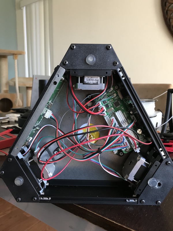
After opening the printer, the first observation I made was that the electronics consist of two PCBs: one does the motor control (called the Motion Controller) and the other handles the LCD and WiFi (called the LCD Controller). This explained why the LCD turned on and even allowed me to navigate through the menu. From what I could tell, the LCD Controller was attempting to talk to the Motion Controller, but the Motion Controller wasn’t running correctly since the firmware had become corrupted.

After looking closer at the boards, I was excited to learn that the Motion Controller uses an STM32F070CB and that the LCD Controller uses an ESP8266. Both of these chips are very well documented and the tools to program them are relatively cheap.

To start, I download the datasheet for the STM32F0x family to look for debug pins. I knew that all the STM32 processors that I’d come across have a Serial Wire Debug (SWD) interface, so things looked very promising.

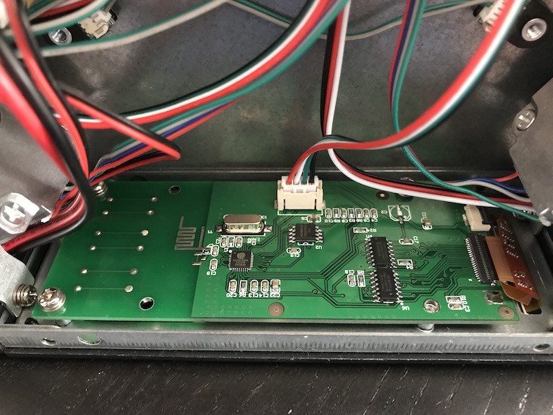
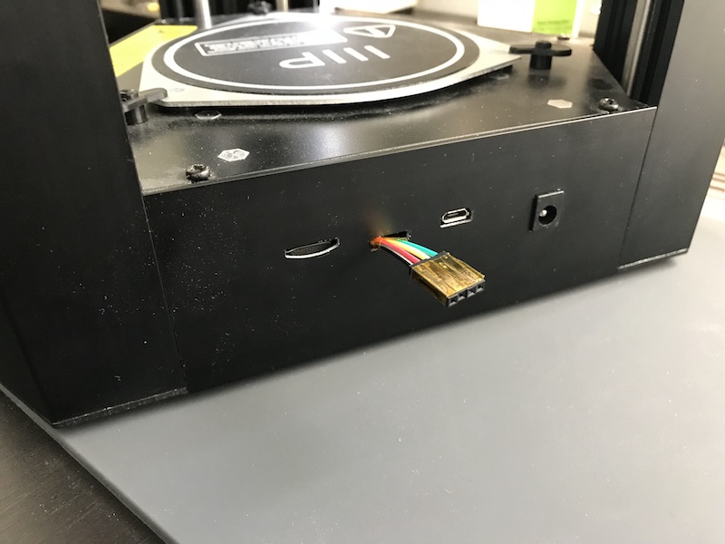
The datasheet showed that Pin 34 (PA13) is SWDIO and Pin 37 (PA14) is SWCLK. So I followed the traces of those pins to this conveniently placed 4-pin header located at the edge of the board. Much to my excitement, the pins for this header are: 3.3V, GND, SWDIO, and SWCLK.

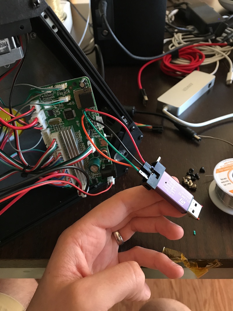
I thought that all I had to do was wire-up my ST-LinkV2 Debugger to the motion controller board, connect to the target, and flash it with the bin file and I’d printing again in no time.

** I’d like to take this moment to say that, in hindsight, I was clearly rushing and not thinking about what I was going to do next…**

I soldered some jumper wires to the motion controller board and used my ST-LinkV2 debugger to connect to the microcontroller. After the debugger connected, I tried flashing it the bin file from the monoprice wiki page…

This is where my memory gets a bit hazy. I hadn’t begun to carefully document all my observations and actions, but I do remember flashing the chip without any problems. I simply selected the firmware.bin file, set the address offset to 0x0800_0000 (the start of flash memory), and hit enter.

The chip flashed successfully, so I rebooted it with hopes of seeing the firmware version on the splash screen, but alas, no luck. Even worse, I realized the big mistake that I had just made… I remembered that the printer ships with a bootloader and that this bootloader was clearly not the built-in stm32 bootloader since it was capable of updating via SD card (built-in bootloader will only update via USB, UART, or I2C). So any custom written bootloader would have to live at 0x0800_0000 since it’s the first thing to run when the microcontroller starts up. So I realized that had just written over the precious bootloader I needed to start the firmware binary in the first place. Lovely.

With the bootloader gone and the application not starting up, I began to wonder what the application binary actually looked like and how it was structured.

This was a good time to step back and learn more about the inner workings of the microcontroller and to take a more methodical approach fixing this printer. Let’s not make things worse by guessing.

The goal now was to learn what a custom bootloader does and what the differences are between a standalone application and a boot-loaded application.

It was around this time when I asked my friend Adam (@adamgreig) about bootloaders and applications. To which he pointed me to the STM32F0 Reference Manual. This manual contains a complete breakdown of the microcontroller. It’s a pretty dense document, but the important items to note are the memory map, vector table, and the general information about the Cortex-M0 architecture.

Let’s start with the easy stuff…

General Information:
Processor: STM32F070CB
Arch: ARM Cortex M0
Instruction Set: Thumb-2
Endianness: Little Endian
Stack Pointer: decrements on push, increments on pop
Program Counter (equivalent to the instruction pointer in x86): increases after each instruction

Groovy. Next let’s look at the memory map…

STM32F0 Memory Map:

We note the relevant address offsets:
Clock Regs 0x4002_1000
Peripherals 0x4000_0000
SRAM 0x2000_0000
Flash 0x0800_0000

But what’s going on at address 0x0000_0000?

Well, it turns out that address 0x0000_0000 is where the microcontroller always begins execution and that the memory at this location is mapped to different address offsets based on a few bits located in the SYSCONFIG register.

I could go into more detail about this, but I feel Jordi Castells has done an excellent writeup about it here: https://jcastellssala.com/2016/12/15/cortex-m0-boot/ (Thanks for the link, @charliex!).

Finally, the interrupt and exception vectors…

STM32F0 Vector Table:

Now you may be asking, what’s a Vector Table?
(I certainly didn’t know what it was when I first heard about it. For most projects, I usually write my code in C using some open-source toolchain which would handle generating the binary containing the vector table.)

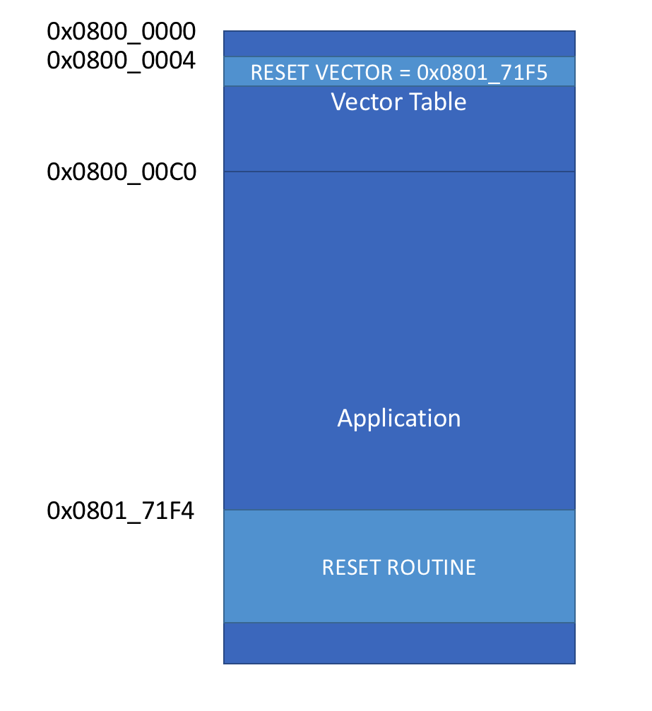
A vector table is a set of 32-bit addresses which live at the start of any Cortex-M0 binary file. The processor uses these addresses as a lookup table for interrupt and exception vectors. For example, every application has a reset vector. This is defined the address location for the reset routine so that when it is invoked, the processor knows where in memory to jump to for executing the reset routine. For the Cortex-M0 family, the reset vector lives at offset 0x04 in the binary. Meaning that if you were to open up any binary built for the Cortex-M0, the second 32-bit word will be the reset vector. Remember this vector as it will prove to be extremely useful later when we get to the disassembly process.

Based on what I had gathered, a standalone application would have a memory map that looks something like this:

The binary for a standalone application is built to be loaded at address 0x0800_0000 (defined in the linker memory configuration script) and the SYSCONFIG register is configured to remap 0x0000_0000 to 0x0800_0000 (flash). This way, when processor starts, it jumps to the reset vector located at offset 0x04.

Now that I had a rough idea of how the binary file is structured, I opened the firmware.bin file and noticed that reset vector is pointing to address 0x0801_71F5. Adam pointed out that in ARM, if you branch to an even address it’s seen as ARM assembly, where as odd addresses are seen as Thumb2. This is denoted using the lsb of the address. Since the STM32F070 is thumb2, the reset vector is actually at 0x0801_71F4.

Note: Endianness is Little Endian

At this point in the project, I purchased Binary Ninja to attempt to disassemble the firmware binary. Using Adam’s Firmware Image tool, I fed Binary Ninja the Entry Point (0x0801_71F4), but I faced the problem of “what’s the start address?”.

We need the start address for two reasons, one if we want to get the application to execute correctly, we need to load it to the right place, and it’s clear that the start address isn’t 0x0800_0000. The second reason we need to know the start address is that the disassembler needs it to find all the subroutines within the binary.

We know the application is hardcoded to execute from some given offset (as any good binary should), but I wasn’t sure if there was an easy way to find this. Using the knowledge that program memory is broken up into pages and that pages have a length of 0x800, I tried entering a few different start addressed into Binary Ninja using offsets that are multiples of that length. After trying 0x800, 0x1000, 0x1800, Binary Ninja found over a hundred subroutines when the offset was set to 0x2000, so it became clear that 0x0800_2000 is the Start Address for the binary.

Now that I knew the start address of the application, I could write a custom bootloader to launch it correctly!

To put it simply, a bootloader can be seen as a self-modifiying standalone application. It has it’s own vector table and routines for loading, checking, and booting applications. But this means that any application written for it, would have to be built for some fixed memory offset outside the bootloaders memory region. Which means the memory map would look something like this:

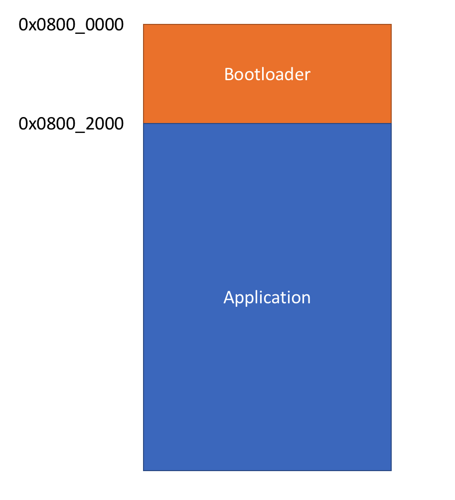
It’s clear that I need a bootloader to start the application and that the only two options I have are to either write my own bootloader or some extract the bootloader from a second printer.

I figured, why not try both?

I still needed to continue printing things for my projects and in the event that I’m unsuccessful in recovering my broken printer, I’d at least have a working one. So I purchased a second printer with hopes that the Read Protection wasn’t enabled on the microcontroller.

When the printer arrived, I wired it up and connected to the micro… and guess what: the Read Protection was enabled.

At this point, I had no other option other than to write a custom bootloader…

I approached writing a bootloader by first putting myself in the shoes of the engineer(s) who built this printer. If I were tasked with writing a bootloader, what would I do?

My first instinct would be to search for an open-source bootloader which supports loading applications from an SD Card. So after some quick googling I found OpenBLT (not to be confused with Open Bacon Lettuce and Tomato). It’s primarily used for STM32 microcontrollers and supports updating firmware via SD Card.

The good news was that OpenBLT supports the STM32F070 and has loads of examples. So I figured this was the right place to start.

Next I outlined the tasks the bootloader needs to perform upon startup:
– Disable all interrupts
– Copy the vector table of the application starting at 0x0800_2000 to the start of SRAM (0x2000_0000)
– Remap 0x0000_0000 to the start of SRAM
– Jump to the reset vector of the application

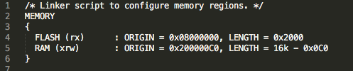
Using the example code for the STM32F090, I modified the linker script to do the following: first, set the flash origin to 0x0800_0000 with a size of 0x2000 (we don’t want the bootloader size to overflow into the application memory), and second, to set the SRAM origin to 0x2000_00C0, so that we could write the vector table to 0x2000_0000 (we don’t want the bootloader overwriting that memory region):

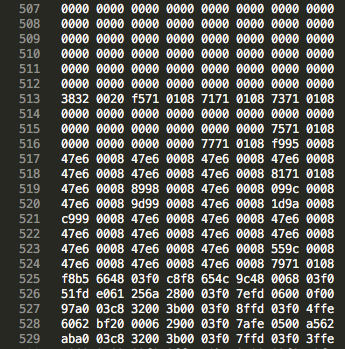
After writing a bootloader to perform the tasks outlined above, I now had a binary file that was smaller than 8K. I knew that I needed the binary to be exactly 8K so that I could merge the application binary with the bootloader. I figured I could just pad the bootloader binary with zeros until it was 8K in size, then append the application to binary using a text editor:

Beginning of hacked_v41.bin (bootloader + application file):

Where the bootloader ends:

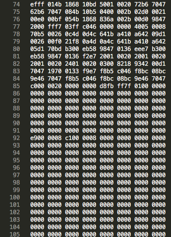
Start of the application:

Now it was time to load the binary and really put all this to the test. I loaded the binary to the chip, setup the debugger to monitor the program counter, and found that the microcontroller was executing the instructions located in application memory! Awesome!

I was *SO* sure that this was it. I power cycled the printer, anticipating the firmware version on the splash screen and…….. no dice. wtf!?

I was a bit disappointed. I wondered what I had done wrong and immediately started sifting through my code hoping for an obvious mistake. After tweaking a few things here and there, I wasn’t making any progress.

I began to question if the LCD firmware version mattered. Perhaps they’d changed the software interface?

So I opened up the working printer, connected the LCD (which I knew had a newer firmware version) to the modified Motion Controller board, and booted it up……. but again, no luck.

At this point, I was curious to see if the Motion Controller was talking to the LCD Controller at all. I pulled out the ye olde logic analyzer and probed the four pins on cable. As expected, two of those four pins were power and ground, and the other two showed some data, but I wasn’t sure what that data was… It looked like serial data.

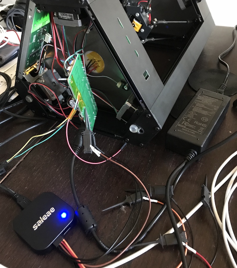
Using the Saleae logic analyzer software, I was able to confirm that it was in fact serial data. To double-check this, I followed the pins to the microcontroller and found that they were wired to the UART1 port.

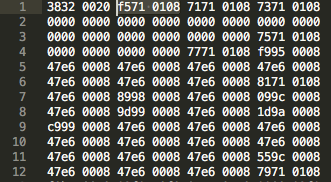
Next, I attempted to decode the data using the ‘autobaud’ feature and found this:

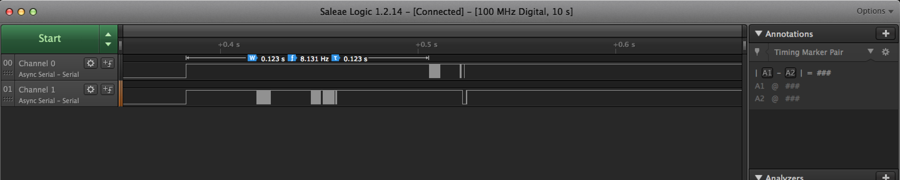
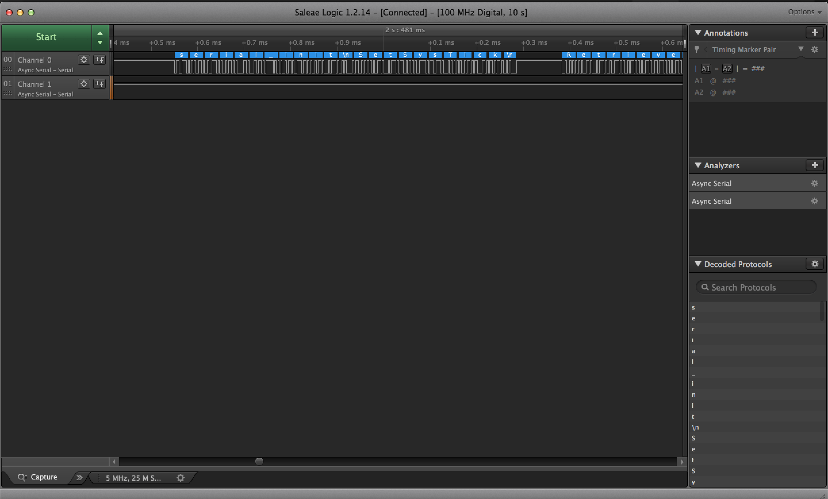
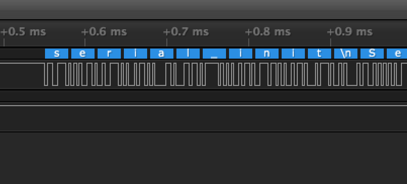
When looking at the microcontrollers TX pin, I observed that the decoded message contained English text, so it was clearly decoding correctly!

Next I probed my working printer to see what the difference was, hoping that this would give me some insight as to what could be wrong.

After gathering data from both printers, I discovered that the baud rate of the microcontrollers UART (with modified firmware) was running at half speed! My first thought was that perhaps my bootloader wasn’t configuring the RCC registers the same way the monoprice bootloader. So I tried a few different things. First thing was to change divider and multiplier settings of the clock, but no matter what values I wrote to RCC registers, I couldn’t get the UART clock rate to change.

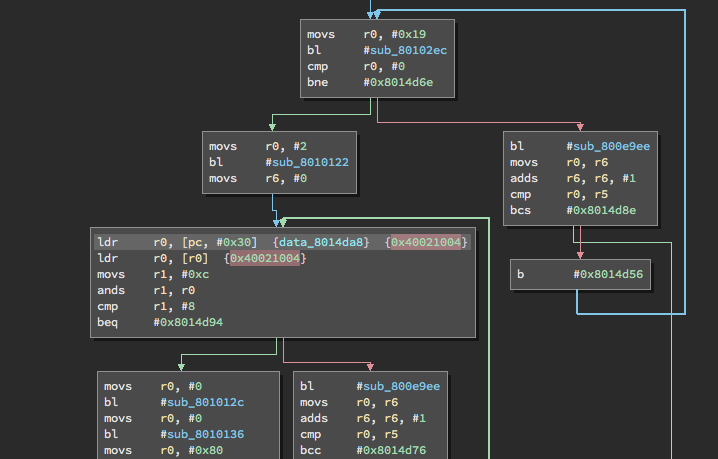
Next, I searched through the disassembled binary to find where the UART clock registers are being initialized and found a subroutine at 0x0801_1ac2 which modifies those registers:

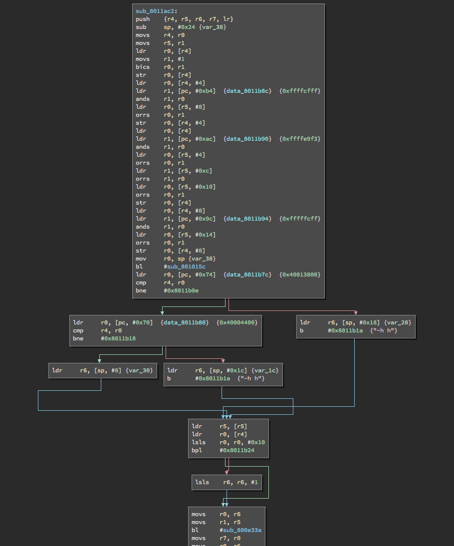
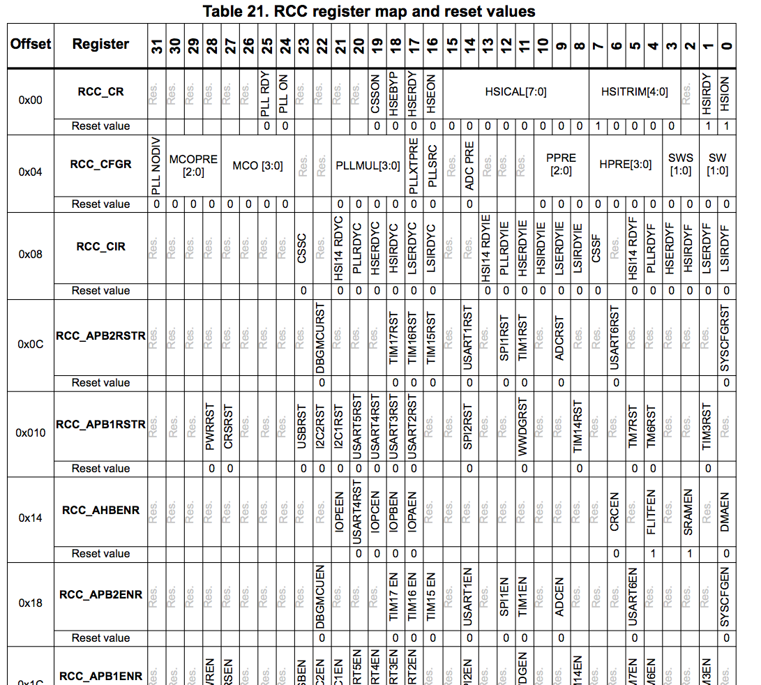
At first glance, we see that application is AND’ing and OR’ing some values against most of the RCC registers, a few of which affect the UART1 clock source. But I’ve tried configuring those bits and I still can’t get it to work…

So I decided to complain about my problems on IRC, and to describe how close I had gotten to getting it to work, and that I couldn’t get the clock settings right… I ended up posted a link to the binary and stepped away. This is when Leo took a crack at looking through the disassembled mess, and had what could only be described as a “Rain Man” moment. He saw through the fog and found an interesting conditional branch located at 0x0801_5A46:

The application was checking the SRAM address 0x2000_0400 to see if it equaled 0xdead_beef, and if it did, it would branch to a bunch of other subroutines… wtf!?

Now guess what the code does if 0x2000_0400 equals 0xdead_beef? If you guessed “modifies the RCC registers”, you’re correct! Not only that, but it does a whole bunch of other stuff too!

Turns out that I didn’t say the magic word

Next I added the following line of code to the bootloader, right before it launches the application:

*(uint32_t*)0x20000400 = 0xDEADBEEF;

I recompiled the bootloader, appended application, loaded it to the printer and…. BINGO! The printer came back to life!

After all that work, the printer was finally back up and operational. You may ask, was all this trouble worth getting it print again? Hell no. Was it worth doing for the learning experience of reverse engineering arm firmware? Hell yeah.

Now, if you have a MP Mini Delta that’s ‘bricked’, I’d first recommend reaching out to Monoprice and asking for a replacement (or for them to fix it). But if ALL options have been exhausted and you’re thinking about salvaging it for parts (or heaven forbid throwing it away), I’ve posted my hacked firmware along with a tutorial on how to recover the printer on GitHub:

WARNING: I AM NOT RESPONSIBLE FOR ANYTHING YOU DO. USE AT YOUR OWN RISK. I DO NOT PROVIDE ANY SUPPORT FOR THIS CODE OR RECOVERY:

https://github.com/arkorobotics/MiniDeltaBootloader

I want to give a huge shoutout to @adamgreig, @leobodnar and @charliex, for without whom this entire project would be dead in the water. Everything I learned here was due to their willingness to answer my silly questions.

For future development, I’ve added an external debug port to the printer 🙂

See you in another five years!
-Arko
@arkorobotics

Nearspace Environmental Chamber

After gaining some experience launching a few High Altitude Balloons (HABs): http://wiki.032.la/habex2 , http://wiki.032.la/habexpico1

I found myself designing smaller and smaller HABs and after the radio cutout on HABEXpico1 (suspected to be due to cold temperatures) I decided it would be a good idea to create an environmental chamber that would replicate the conditions of nearspace.

The conditions of nearspace aren’t too kind to electronics. Air temperature can be anywhere from -60C to +40C, the air pressure at the average burst altitude of 30,000m (100,000ft) is 1% of the pressure on the ground. Electronics dependent on convection for cooling can easily overheat, and the cold temperatures can shut down electronics if they are not rated for those conditions and if the insulation isn’t sufficient.

Expected environmental conditions:

•Air Temperature:  -60C to +40C
•Pressure:  0.01atm (1010Pa) to 1atm (101325Pa)
•Winds:  0mph – 100mph
•Forces:  up to 10g
•Humidity:  0% – 100%
•Solar Heat (Irradiance): 180 W/m^2  –  340 W/m^2
 envirograph
Heat Transfer Diagram:
heatexchange

The goal was to build a thermal/vacuum chamber for $100-200 capable of testing and answering the 3 following questions:

1) Can your HAB survive the expected temperatures?

2) How well does your insulation work?

3) Does your HAB overheat? (Do your parts need cooling?)


Now you can attempt to do thermal modeling… but that gets tricky. You can save time and get good results by just testing it.

modeling


For each environmental condition you can replicate the follow conditions using the following:

•Air Temperature -60C to +40C:                   Dry Ice, Hair Dryer
•Pressure 0.01atm to 1atm:                             Refrigerator Pump
•Solar heat 180 W/m^2  –  340 W/m^2 :    Light Bulb, Heat lamp
•Winds/Forces up to 10g:                                Fan/Stairs (Ed Method)
•Humidity 0% – 100%:                                       Spray Bottle
The thermal/vac chambers design was then CAD’d:
envchamber3          chamdiagram
On the left is a vacuum pump connected to a schedule 40 PVC tee with 1/2″ thick polycarbonate lids sealed by silicone rubber. Outside you can see a light bulb facing the window which is used to replicate the expected solar flux. In the original design, a peltier cooler was interfaced with a copper rod running from the outside into the chamber was used to cool the HAB inside. Due to a large thermal gradient across the copper rod this cooling system was scraped. The new cooling system was not only cheaper, but more effective. The solution was to wrap a small flat piece of dry ice with cloth and tape it to one side of the hab then hang the hab from fishing string inside the chamber. This would result in one side of the HAB getting very cold (-40C or so). This however requires you to run the pump continuously since the dry ice sublimates creating CO2 gas.  If you were to turn on the light bulb, you would notice one side getting warmer while the sides in the shadows remain cold.
9617079873_5dc762b936_b
Dry Ice & cloth taped on one side…
9620308350_540a28dc1b_c
You can see the light bulb, chamber, and the HAB inside..
9514411346_04a4c998e6_b
I ran kaynar wire through the top plate and filled it with epoxy. Holds up under pressure!
GOODDATA_color

These were the results. The one side facing the “sun” got to about 28C (RED), while the cold side facing “deep space” aka dry ice got the outside of the insulation to about -40C (BLUE), and the inside of the HAB slowly moved down to about 10C (GREEN). Not bad, but not great. The problem with this setup is the fact that the dry ice is thermal interfaced with by conduction, rather than radiation. In a proper thermal vacuum chamber a shroud with liquid nitrogen tubes is run through the walls to produce cold walls. The walls are coated with a material such as black paint (high absorptivity), this forms good radiative thermal coupling. One could improve the design by having this and even placing it on a lazy susan to allow the hab to rotate and spin while the sunlight is applied. However, the setup would cost more than the original budget of “under $200”. Please note that this a “build at your own risk” project. I’m not responsible if your chamber implodes or hurts anyone. Also, do not cool down the PVC itself, that could make it very fragile.

Here’s the cost breakdown:

Environmental Test Chamber – Online & Easy    
Part Source Cost
4″ x 4″ x 4″ Schedule 40 PVC Tee http://www.homedepot.com/p/DURA-4-in-x-4-in-x-3-in-Schedule-40-PVC-REDUCING-Tee-SxSxS-401-422/203225320?MERCH=REC-_-product-6-_-203217750-_-203225320-_-N#.UhFTQpKxVjI $12.68
Extreme-Temperature Silicone Rubber http://www.mcmaster.com/#8632k42/=o4ghu7 $9.93
1/2″ thick, 6″ x 6″ http://www.mcmaster.com/#8560k274/=o4gi8k $25.38
Vacuum Pump – 2 Stage – 25micron http://www.amazon.com/Vacuum-Pump-2-Stage-Rotary-R410a/dp/B008BTM2N0/ref=sr_1_9?s=industrial&ie=UTF8&qid=1376867868&sr=1-9&keywords=Vacuum+Pump+2-Stage $87.00
Tubes/Connectors Hardware Store $40.00
Light Bulb & Fixture http://www.amazon.com/Zoo-Med-Economy-8-5-Inch-Chrome/dp/B0002DIWUU/ref=sr_1_1?s=industrial&ie=UTF8&qid=1376868265&sr=1-1&keywords=clamp+lamp+6in $15.73
Dry Ice Meat Market $5.00
Total Cost: $195.72
Environmental Test Chamber – Lower Cost
Part Source Cost
4″ x 4″ x 4″ Schedule 40 PVC Tee http://www.homedepot.com/p/DURA-4-in-x-4-in-x-3-in-Schedule-40-PVC-REDUCING-Tee-SxSxS-401-422/203225320?MERCH=REC-_-product-6-_-203217750-_-203225320-_-N#.UhFTQpKxVjI $12.68
Silicone Rubber Hardware Store $4.00
1/2″ thick, 6″ x 6″ http://www.mcmaster.com/#8560k274/=o4gtij $25.38
Fridge Pump Junk Yard/Craigslist $20.00
Tubes/Connectors Hardware Store $40.00
Light Bulb & Fixture http://www.amazon.com/Zoo-Med-Economy-8-5-Inch-Chrome/dp/B0002DIWUU/ref=sr_1_1?s=industrial&ie=UTF8&qid=1376868265&sr=1-1&keywords=clamp+lamp+6in $15.73
Dry Ice Meat Market $10.00
Total Cost: $127.79


In my talk I discuss the solutions to solving a hot or cold hab: http://arkorobotics.com/data/UKHAS_2013_arko.pptx


In my extended talk I also discuss solving software, radio/hardware configuration, and EMC (electromagnetic compatibility): http://arkorobotics.com/data/UKHAS_2013_EXTENDED_arko.pptx


HABEXpico4

So as the journey toward creating a HAB that you can accidentally breath in continues… I finally got HABEXpico4 working! Seeing how HABEX1 weighed 6.00lbs, HABEX2 weighed 4.00lbs, and HABEXpico1 weighed 250g, it’s pretty amazing to see HABEXpico4 around 12g with battery/insulation/antennas. So what happen to HABEXpico 2 and 3? HABEXpico2 was scrapped after the boards were made because it couldn’t be light enough or power efficient, and HABEXpico3 was small but not small enough and used software serial (very stupid). After messing around with the design, I realized it’s better to just merge the design with M0UPU‘s PAVA8 which used the real hardware serial ports. The only difference now is that my design uses a Si4464 which can transmit and receive data. Plus this means shared code! So any improvements software wise would help others. So huge thanks to M0UPU for his help in all this.

The boards were manufactured by Hackvana who made an insanely good offer… $21 for 10 of these 0.8mm/white HAB pcbs! Totally recommend them for a good quality low cost PCB run.


Programmable Mars Watch for $50

We have all heard by now that Curiosity, JPL/NASA’s new rover, has successfully landed on mars and is now roving the surface 🙂  http://www.jpl.nasa.gov/msl/

Here’s the thing with mars though.. time is kept differently there. This is because mars itself rotates a little slower than earth. Rather than a solar day taking 24 hours like it does here on earth, mars has a solar day of 24 earth hours 39 earth minutes and 35 earth seconds. This proves to be a pain when it comes to timekeeping. If you set your normal earth watch to the exact mars time at that moment, you will lose a mars second every 36 seconds on your watch. This is because earth seconds and mars seconds are different. Since you want to have a 24 hours day (Sol) you must scale the 24 earth hours, 39 earth minutes and 35 earth seconds into 24 mars hours. This redefines a second: 1 mars second = 1.0274912510416665 earth seconds. Side note: a mars day is called a “Sol”.

More on timekeeping on mars:

http://www.giss.nasa.gov/tools/mars24/help/notes.html

http://en.wikipedia.org/wiki/Timekeeping_on_Mars

NASA’s official mars clock http://www.giss.nasa.gov/tools/mars24/

Awesome Android and iPhone app written by Scott Maxwell (@marsroverdriver):

https://play.google.com/store/apps/details?id=org.scottmaxwell.android.marsclock


Now who really needs this? The answer is the mars rover team. In order to have an efficient day driving on mars, the rover driving team lives on mars time. From what I can tell, it seems painful. However, I wouldn’t mind doing it if it was for the opportunity to drive a rover on mars 🙂  Although I don’t live on mars time and am not involved in the driving process, I still have this odd fascination with keeping track of mars time. I remember back in 2004 a local jeweler has figured out how to make analog mars watches: http://marsrovers.jpl.nasa.gov/spotlight/spirit/a3_20040108.html  This was too cool! I realized I couldn’t dish out $300 (a lot of money for a kid back then) to get a watch I wouldn’t need. Most of the people who bought them were apart of the mars team anyway.

Fast forward 8 years and now we have a new rover on the surface of mars, and all though I had a very very small role in the mission I’m still no where near having to live on mars time, but who says I can’t have a mars watch anyway? 😀


With the knowledge of keeping time on mars and a good background in embedded systems I figured it shouldn’t be too hard to modify a digital watch. I searched around and found the perfect watch for this project:

Ti Chronos ez430 915Mhz   –    http://processors.wiki.ti.com/index.php/EZ430-Chronos

Buy Here:    Ti-Store   ,   Digi-Key   ,   Mouser   ,  Newark


The watch comes loaded with features:  rf communication, timers, alarms, accelerometer, barometer, and a temperature sensor.

The watch also comes with an rf to usb module, usb programmer/debugger, and a screw driver. For $50, it’s a steal. I looked over the example code before purchasing it and discovered that I could modify the timer that controls watches master timer. So I put in the order, rewrote the timer code (which I go into detail below) and modified the date files to keep track of sol’s rather than days.


So lets dive right in.

First off, if you want to develop, you will need to download Code Composer Studio (http://processors.wiki.ti.com/index.php/Download_CCS ) which will come with the default watch firmware (also available here: http://www.ti.com/lit/zip/slac341 ).  If you just want to flash the watch with the mars watch firmware scroll down to the “Firmware:” link and follow instructions below. So anyway, the processor on the watch is based on the TI MSP430 and has several timers. The default program (ez430_chronos)  that keeps track of the time is located in clock.cclock.h, timer.c, and timer.h. The first thing we need know is that the clock source is a 32.768khz internal crystal. This  internal clock is connected to Timer 0. The code in the function void Timer0_Init(void) found in timer.c configures the timer to count continuously up to 32768 (TA0CCR0 register) which takes exactly 1 second to reach. Once the timer reaches 32768 it triggers an interrupt which calls the function void clock_tick(void) in clock.c which takes care of the clock logic (when to increment hours, minutes, and seconds). Since the Sol is 24 mars hours the logic will remain the same and we will mess with the timer that triggers the mars second. What we want is the timer to go off every 1.0274912510416665 earth seconds so that it would be the equivalent to 1 mars second. So you essentially want to scale up and count that extra 0.0274912510416665 earth seconds. Which means you need to increase the TA0CCR0 register value. This requires some really simple math:

Here we do some basic scaling and discover the new TA0CCR0 register value to be 33668.83… but we have a problem now.. the register isn’t a decimal value it’s a 16bit value. So that means we can either choose 33668 or 33669 to count to. So I decided to calculate the error for each value, expecting less error if I went with 33669. The error for 33668 is losing 1 mars second every 0.4 Sols and the error for 33669 is gaining 1 mars second every 1.3 Sols. Makes sense since 33669 is closer to 33668.83 than to 33668. So I began to wonder how bad does this drift really become? To drift 1 mars minute it would take about 78 Sols and to drift 8.57 mars minutes would take about 1 martian year (approx 668.6 Sols).

As for calculating Sol, I modified date.c and date.h so that when 24 hours is reached it increments 1 Sol rather than day and month. The Sol is displayed below the time. The Sol tracking works just fine but the back end code is a little messy so I will clean that up asap.


After some testing and comparing against the mars24 and mars clock programs I concluded that the clock drift isn’t too bad and could easily be changed by going into the time set menu by holding the “*” button. You can also set the Sol by holding the “#” button. Worst case, 2 years from now you may get 5 minutes late to something if you relied on the watch.


This all took me about 5 hours to figure out, write, and test. Plus another hours to write this blog. The code is not very complete, but is a work in progress. I would say that it has the essentials to a mars watch, and that the bells and whistles will come late. In the coming weeks I will try to see if I can build in some compensation for the drift or modify the timer some how to get a more accurate reading. I will also clean up the sol code and make it so that you can track both earth and mars time in one watch. I figured it’d be nice to get the code out there so others who want to modify their watches into mars watches can do so.


UPDATE:  Jon Hollander made a comment on hackaday with a very elegant solution to loosing that 0.833 in 33668.883. Rather than just picking 33669 and dealing with the loss of 0.166 he recommended switching between 33669 and 33668 until you average 33668.883. Turns out if you replace the  TA0CCR0 += 33669;  in Timer.c with the following code below you can greatly increase the accuracy. The code below will count 33669 5 times then 33668 1 time thus averaging out the counting to 33668.833. Hooray for minimizing error!

New Timer0 Code:

static u8 dither_counter = 0;

if(dither_counter < 5)
{
TA0CCR0 += 33669; //33669
dither_counter++;
}
else
{
TA0CCR0 += 33668; //33668
dither_counter = 0;
}


Source Code:  https://code.google.com/p/ti-chronos-mars-watch/source/browse/#svn%2Ftrunk%2FMars%20Watch%2Fez430_chronos

Firmware:

Just download the txt and upload it to your watch!

Download: http://ti-chronos-mars-watch.googlecode.com/files/ez430_chronos_915MHz.txt

To upload the firmware you can select the firmware txt file and upload it using the Chronos Control Center software that comes with the watch or download the software here http://www.ti.com/lit/zip/slac341 . The connection is established through the USB wireless access point (included with the watch).


Here’s a demo:


Unlock and Backup your Ninja Tel phone

Disclaimer: I’m a n00b. My process was successful, so it must be really easy to do this 🙂

So if you are one of the lucky few to have been given a ninja phone (thanks ninjas!) this post may help you. I’ll go through the process I went through to unlock my bootloader and back up my phone.


Before you start, plug your ninja phone into your computer and put it into hard drive mode. Take all your photos out in case something goes wrong.


Fancy phone 🙂
http://i.imgur.com/friEn.jpg

Ok, first things first, here are two links that will help (thanks to davo for sending me these links):

1) This all-in-one tool will help you if you are a n00b like me: http://forum.xda-developers.com/showthread.php?t=1676686 Go there and download the HTC One V AIO Kit, and boot it up.

2) This is a link that will get you all the tools, roms, etc that you will ever need: http://forum.xda-developers.com/showthread.php?p=27509958


Instructions:

0) Unpack the “One V 1.1.exe” and it’s data files from the first link, you should see this:

htcv

1) Select “1. Install HTC Drivers”, click “Go”.

2) Go to http://www.htcdev.com/ and register and account.

3) Click “Unlock Bootloader”, Select “All Other Supported Models”, then click “Begin Unlock Bootloader”, accept everything and get to page 3 where you have to input the Token, leave this window open.

4) Connect your ninja phone to the computer, and run the “One V 1.1.exe”

5)  Select “3. Get Token ID”, click “Go”. This will get the Token for you, right click on the cmd and select “mark” then select all of the token, this copies the token (instructions are given during the “Begin Unlock Bootloader” process).  Close the cmd.

6) Go to the htcdev site where you should have window open to page three, and paste in that tokin into the field, click “Submit”.

7) You will receive an email with the “Unlock_code.bin”, download and move that file into your data folder (/One_V_All-In-One_Kit_v1.1/Data/)

8 )  Run the “One V 1.1.exe”, Select “5. Unlock Bootloader”, click “Go”. Then select yes (select with volume button, press power to OK it) when prompted for unlocking the bootloader. You should see this:

http://i.imgur.com/FvHS0.jpg


9) This voids your warranty.. lol?

10) Congrats, you’re unlocked!


Onward to Backing up:

0) Reboot.

1) Put a microSD card inside

2) Open up “One V 1.1.exe”, Select “ClockWorkMod”, Click “Flash Recovery”. This will replace a part of the recovery partition on the phone allowing you to use the tool to recover the phone.

3) Once that’s done, the phone will automatically reboot. Mine froze up when rebooting, but after holding the power button and resetting it it was fine.

4) Open up “One V 1.1.exe”, Select “Boot into Recovery”, Click “Do Command”.

5) This will reboot the phone into recovery mode.

6) Look at the phone, the phone should have some options, select “Back up and restore”.

7)  Look at the phone, once that’s done, it will give you a “Reboot” option, select that.

8) You’re done! Everything is on the sd card now!


You can feel free to screw around with the phone now. I’m not responsible for any of you screw ups 😀

Happy hacking!


http://i.imgur.com/81jtS.jpg

Simple Hexapod Project – Part 1

So aside from the hush hush projects, I’ve recently picked up a new project on the side that I can talk about 🙂

This project has been started at Nullspace Labs working along with charliex and mmca.


I’ve always wanted an army of loyal robots to follow me around.. what better than a 6 legged crawler!

The goal has been to create a new and simple hexapod design that can be easily laser cut and assembled in one night. Oddly enough I’ve been CAD and rebuilding one each night at NSL. The process from design, to cad, to laser cut and assembled can take about 4-5 hours.. which is just mind blowing fast.


Here’s a shot of the original design from CAD to real life prototype:


It’s crazy to see it come together so quickly.

Now, the prototypes design has several flaws.. For example the joints are very wobbly. So to help this I fit the servo mount into the acrylic body to make a tight fit. Then I brought the boards closer together to decrease the bending at the joints.


So with the design slightly improved I’m going to move on to making a much more sturdy base. The base is currently the most wobbly part. Once the base is fixed up I’ll be ready to add the electronics / servo controller. Lots to do, but I figured I’ll give a quick peak at one of the things I’ve been working on.


Gonna keep on prototyping.. more to come! I’ll post CAD files when the design isn’t changing every 5 minutes 🙂


New CAD:


Layerone 2012 Autonomous Car “Stanley Jr” Badge Hack

Woo! Haven’t been blogging much since most of my recent projects have required me to keep quiet until they are done.. it sucks not to be able to share a lot of what’s going on 🙁

Anyway, with more to come I thought I’d share a recent project that was completed within a few hours of tinkering and hacking.

But first a quick back story, I had the great pleasure to be running the Hardware Hacking Village this year at Layerone 2012 along side with Krs, Charliex, and Mmca of Nullspace Labs. Layerone is a security conference that covers everything from computer security to lockpicking and hardware hacking. Each year since last year, Layerone has had electronics badges and has provided a working space for attendees to build and hack their badges. What happens is we pretty much pack up most of our equipment at the Nullspace Labs Hackerspace in Downtown LA and bring it down to the conference. This year we had 12 metcal solder stations and 10 microscopes along with many tools such as heat guns and tweezers to help you build and hack your badge. Charliex, Krs, and Mmca spent the last 2 week designing, revising, ordering, testing, and building them (along with some help of a few NSL members, fiances,  and myself). With only 4 hours and 45 minutes left to spare, we all arrived at the Layerone hotel at 4:15am.. good times.

This years badge was a bullet proof pcb that was half an Arduino and half an RC car controller (with traces running between them allowing you to control it with the Arduino). When you bought the kit to populate the boards you also received an RC car which you could interface with your badge. I felt that human control was fun, but thought it would be awesome if my badge could just follow me and avoid obstacles so I wouldn’t have to carry it around my neck 😛

I,  knowing ahead of time what the badge would be, decided to order a few parts a week in advance so when I had some time I could build and hack my own badge. I should note that there was a badge hacking competition held at the conference, and very fairly, I was disqualified due to prior knowledge 😉 no problem though, I have an awesome car that drives itself! I should note that you should check out Charliex’s blog which has a much more in depth write up about the badge hacking competition. Mad props to Jason who made a morse code keyer and Funsized who made an EL-wire/IMU based badge.


Back to the car, I purchased the following:


Sparkfun Prototyping Shield: ($14) http://www.sparkfun.com/products/7914


Parallax Ultrasonic Range Sensor PING))): ($30) http://www.parallax.com/….


Servo Motor Hitec HS-81: ($16)  http://www.xheli.com/hrc31081s.html?gclid=CLvBwq6hpLACFY4FRQods2JqXg


and  few wires..


What I decided to make was an autonomous car that would use the badge as a base/brain, the car as the controls, and the ultrasonic sensor on top of a servo for finding and avoiding obstacles.


I ended up naming it “Stanley Jr” after the notorious “Stanley” DARPA Grand Challenge car built by Stanford’s team. I will take this moment to note that if you are a GoogleX Labs employer (or know of one) and are looking for someone madly obsessed with self-driving cars to work on your team, I will gladly send you my resume 😀 I build robots too!

So between helping others build their badges for the con, I was able to piece together the hardware in under an hour. After some troubleshooting I had a non-continuous hour of coding. The results aren’t great by a long shot when it comes to autonomous vehicles, but I do plan to improve the code and make Stanley Jr smarter. As of right now, the ultrasonic pans in three positions, left 45deg, center 90deg, and right 135deg. Since the steering is practically trianary (left, center, right) I figured it’d be best to sweep the three directions it had available, move a small step, and then repeat. After solving a few bugs and fixing  other peoples badges I had some working code. The goal the vehicle is given is to drive in the direction in which it sees the furthest distance. If the distances on all three options is too small, it will not make any moves to avoid accidents. Improved code that is currently in the works has a mode where it backs up in the direction it came in and then picks the alternative direction from that previous move.

The proper way to go about this control system would be to have a smooth sweeping of the ultrasonic sensors to obtain a more accurate model of the world. The car would then be given the goal of “drive forward and don’t hit anything”.  Then rather than “sweep, stop, think, act, repeat”, it would be constantly moving at a regulated speed based on how far it can see. Once objects to its center get close it will pick the furthest distance out and go in that direction with the intention to return to wheels center. So lots to come 🙂


Stanley Jr is pretty stupid at this point, but not bad for about 2 hours of work. I plan to drastically improve the code and eventually move to a wheelchair base system that can drive around a beer keg delivering beer to bystanders while using a Microsoft Kinect to both recognize people and avoid objects.


Here’s a video and few pictures of the car:


Be warned, I wrote this code in a rush, it’s no where near complete or smart. Here’s the code:


// Layerone 2012 Autonomous Car Code
// By: Arko

#include <Servo.h>

Servo myservo;

int pos = 0;

const int pingPin = 2;

long world[4];
int world_count = 0;

void setup()
{
Serial.begin(9600);
myservo.attach(3);

pinMode(13,OUTPUT);

pinMode(9, OUTPUT); // BACK
pinMode(8, OUTPUT); // FWD

pinMode(7, OUTPUT); // RIGHT
pinMode(6, OUTPUT); // LEFT

}

void loop()
{

digitalWrite(6,HIGH);
digitalWrite(7,HIGH);
digitalWrite(8,HIGH);
digitalWrite(9,HIGH);

digitalWrite(13,HIGH);
// Obtain Environmental Model

world_count = 0;
delay(500);

for(pos = 45; pos < 180; pos += 45)
{
myservo.write(pos);
long duration, inches, cm;
delay(500);
pinMode(pingPin, OUTPUT);
digitalWrite(pingPin, LOW);
delayMicroseconds(2);
digitalWrite(pingPin, HIGH);
delayMicroseconds(5);
digitalWrite(pingPin, LOW);

pinMode(pingPin, INPUT);
duration = pulseIn(pingPin, HIGH);

// convert the time into a distance
inches = microsecondsToInches(duration);
cm = microsecondsToCentimeters(duration);

world[world_count] = cm;
world_count++;

Serial.print(inches);
Serial.print(“in, “);
Serial.print(cm);
Serial.print(“cm”);
Serial.println();

delay(1000);
}

Serial.print(“World: “);
for(int c=0; c<3; c++)
{
Serial.print(world[c]);
Serial.print(“,”);
}

digitalWrite(13,LOW);

delay(100);

// Control

// Direction 0 – LEFT
// 1 – CENTER
// 2 – RIGHT

if((world[0] > world[1]) && (world[0] > world[2]) && (world[0] > 30)) // Go Left
{
digitalWrite(6, LOW);
digitalWrite(7, HIGH);
digitalWrite(8, LOW);
Serial.println(“LEFT”);
}
else if((world[0] < world[2]) && (world[2] > world[1]) && (world[2] > 30)) // Go Right
{
digitalWrite(6, HIGH);
digitalWrite(7, LOW);
digitalWrite(8, LOW);
Serial.println(“RIGHT”);
}
else if(world[1] > 30) // Go Center
{
digitalWrite(6, HIGH);
digitalWrite(7, HIGH);
digitalWrite(8, LOW);
Serial.println(“CENTER”);
}
delay(500);
}


long microsecondsToInches(long microseconds)
{
return microseconds / 74 / 2;
}

long microsecondsToCentimeters(long microseconds)
{
return microseconds / 29 / 2;
}

Ardrone Hacking

I did this a while back at NSL.. not really a whole lot of hacking involved really, but I thought I’d share.


If you’d like to have ftp access to your ardrone you can follow these step:

1) Plug in your battery and using your laptop, connect to your Ar.Drone.

2) Download and open Putty (or whatever you use to telnet), telnet to 192.168.1.1 Port 23

3) ??? (This means you’re in, no password)

4) Profit

5) Congrats you’re in, but let’s make this easier to hack, let’s get it to give us ftp access to the root. cd into ‘/etc’

6) vi inetd.config

7) Change the first line “21 stream tcp nowait root ftpd ftpd -w /data/video” to “21 stream tcp nowait root ftpd ftpd -w /”

8) Open your web browser or filezilla and ftp into your Ar.Drone: ftp://192.168.1.1

9) Enjoy


The Ardrone uses AT commands, using google I found: https://projects.ardrone.org/boards/1/topics/show/852


I made a really quick hack while back where I replaced the terrible battery connector they use with a deans connector (http://www.wsdeans.com/products/plugs/ultra_plug.html). So now I can connect the helicopter batteries I have lying around. It allows me to put in higher mAh batteries for longer flight time, which is always good 🙂


Here’s the hardware teardown specs:

Processor Board: (Front)

  • Parrot 6 – CPICS01192A 1022 R1A 7POF47424.00 ARM
  • 01A17 D9HSJ M LTX1
  • Atmel 58A870 AT73C246 0P0987A 1025
  • ROCm ATHREOS AR6102G-8M2D 007K0523.51A F52257.1K 1023
  • SMSC USB3317 1409600C CKR
  • 32.000Mhz Crystal

(Back)

  • 1012 I-2 29FIG08AAC WP C BTT9

Navigation Board:

  • Microchip PIC24HJ 16GP304 I/PT 1019K WB
  • 6L04STE 1017 V5B
  • Invensense IDG 500 143363-H AL1020C
  • 043 U018 206


iClicker Hacking – Part 1

Before I start, I’d like to note that this is my first reverse engineering project.

So the story here starts with me taking a class that required me to purchase one of these iClicker’s ( http://www.iclicker.com/Products/iclicker/ ), otherwise I wouldn’t get “participation” points in class :/ So I purchased one and booted it up during lecture to “participate”. It was neat to see some tech in the classroom, but the material wasn’t any more interesting, so I decided to tear this thing apart… I busted out my utilikey and tore it apart mid-lecture.

At this point the professor noticed all the students were “participating” except me. She then walked up to my desk and noticed the iClicker completely torn apart and asked “What are you doing?” to which I responded “Opening this thing up..” and she responded with “This is not apart of the lecture, you shouldn’t be doing this in class. This is very important you should be paying attention.”  I figured it’s time to protect my grades so I said I would clean it up right away, and did so.. (unhappily)

I snapped a few shots of the tear down before doing so..

Here we see the Buttons “A”  “B”  “C”  “D”  “E”  and “ON/OFF”.

Noticed the RF hardware consisted of an XE1203F ( http://www.semtech.com/images/datasheet/xe1203f.pdf ) which does ISM band (iClicker is configured for 900Mhz)

Discovered the microcontroller is an ATMega8A ( http://www.atmel.com/dyn/resources/prod_documents/doc8159.pdf )  and best of all.. the ICSP pads are broken out for you already!! At this point I was hoping that the security bit wasn’t set so I could dump the firmware and EEPROM.


I later got to my setup at Nullspace Labs ( http://032.la/ )  and soldered on a 6pin header for the ICSP line. Then connected my AVR Dragon and attempted to dump the firmware and EEPROM from the ATMega8A with an external power supply connected to the power leads for the battery. As soon as I attempted the read, the iClicker reset itself. So I figured the power management must be doing some funky things, so lets by pass all that and go directly to the ATMega8A’s VCC and GND line. I soldered on some kynar wire to pin 4 (vcc) and pin 5 (gnd) and attempted the read again..

Success!! The security bit was never set! So now that I could communicate with the chip, I decided dumped the firmware and EEPROM. (Reversing in IDA to come in Part 2)


At this point I realized the hardware ID must be in the EEPROM, so I went exploring looking for “3300B586” which is the hardware ID written on the back of the device:

I noticed at line 0 column A the sequence “3300B5”, huzah!  At this point I could just modify this and change the hardware ID of the iClicker!


Next I decided to listen to the communication between the ATMega8A and XE1203F by sniffing the SPI bus, following the datasheets I soldered up some wire to the SPI lines. Once the wiring was done I used my handy AnnaLogic to sniff the SPI bus.

AnnaLogic (16-channel logic analyzer) from Nullspace Labs (available for purchase here for $40:  http://www.nullspacelabs.com/catalog/products.php?5&sid=mkkhjkoj10qo012972ufdfhka3 ) Totally easy to use and it fits in an egg!!


Once I powered up the iClicker (note: it’s not connected to an instructor machine) I began the sniffing and pressed the following sequence of buttons:  A  B  C  D  E . I noticed that there was only data on the Slave Input lines, which makes sense since there is no instructor machine to send data back. Between each button I pressed only one byte was changed, and it doesn’t seem to be as intuitive as ‘A’, ‘B’, ‘C’,’D’,’E’. Instead A = 177 (0xB1) , B = 181 (0xB5), C = 189 (0xBD), D = 190 (0xBE), E = 186 (0xBA).

Next I need to capture some traffic between my iClicker and the instructor machine to see a full cycle of registering the iClicker to the instructor machine, voting and receiving confirmation that the vote went through.. I’ll leave that for Part 2.

Please note that I will NOT be doing this packet capture in the classroom (it’s no place for learning anyway), I’ve decided to purchase an instructor base station to prevent any issues with my school. Plus it gives me control to test and try out things I normally wouldn’t be able to do.


For the mean time I need the clicker for lectures so I’ve poked a hole into it.. totally looks normal 🙂


Next up.. reverse engineering the firmware in IDA, stay tuned for Part 2:


So far the only defeat has been spoofing other iClicker hardware ID’s by reprogramming the EEPROM (thankfully iClicker never set any security bits 🙂 ) It’s not much yet, but next up is to reverse the firmware and figuring out how the packets are sent, handled and then to create a new firmware with some extra features. A few new features I’ve thought of are listening in to other iClickers, submitting and spoofing as other iClickers, and making a  general purpose ISM band radio.


Interested in hardware hacking?   Layerone 2012 http://www.layerone.org/  🙂

Juki 360 Renovation

So a few weeks ago Nullspace Labs got an old pick’n’place and decided it was time for a renovation with much newer technology. Charliex and mmca for the past few weeks have been working non-stop on rebuilding this thing. It went from a busted old computer running CP/M with “ok” precision to a higher precision, computer control/vision machine which controls the pnp with an Arduino! Charliex’s blog explains the process it has gone through is great detail (it is a must read): http://charliex2.wordpress.com/tag/juki/

I have been fortunate to have had a small role in this project by drafting up/CADing some of the new parts designed by mmca for the machine!  Here are a few pictures from the Solidworks files for what is to come!


Here is a plate with an adjustable height where components are placed for the pnp to pick them up!


Here is the new head plate adding the capability of 360 component rotation, camera mount, and a pneumatic solder paste applier!


Also, go to Layerone 2012: layerone.org