Nearspace Environmental Chamber

After gaining some experience launching a few High Altitude Balloons (HABs): http://wiki.032.la/habex2 , http://wiki.032.la/habexpico1

I found myself designing smaller and smaller HABs and after the radio cutout on HABEXpico1 (suspected to be due to cold temperatures) I decided it would be a good idea to create an environmental chamber that would replicate the conditions of nearspace.

The conditions of nearspace aren’t too kind to electronics. Air temperature can be anywhere from -60C to +40C, the air pressure at the average burst altitude of 30,000m (100,000ft) is 1% of the pressure on the ground. Electronics dependent on convection for cooling can easily overheat, and the cold temperatures can shut down electronics if they are not rated for those conditions and if the insulation isn’t sufficient.

Expected environmental conditions:

•Air Temperature:  -60C to +40C
•Pressure:  0.01atm (1010Pa) to 1atm (101325Pa)
•Winds:  0mph – 100mph
•Forces:  up to 10g
•Humidity:  0% – 100%
•Solar Heat (Irradiance): 180 W/m^2  –  340 W/m^2
 envirograph
Heat Transfer Diagram:
heatexchange

The goal was to build a thermal/vacuum chamber for $100-200 capable of testing and answering the 3 following questions:

1) Can your HAB survive the expected temperatures?

2) How well does your insulation work?

3) Does your HAB overheat? (Do your parts need cooling?)


Now you can attempt to do thermal modeling… but that gets tricky. You can save time and get good results by just testing it.

modeling


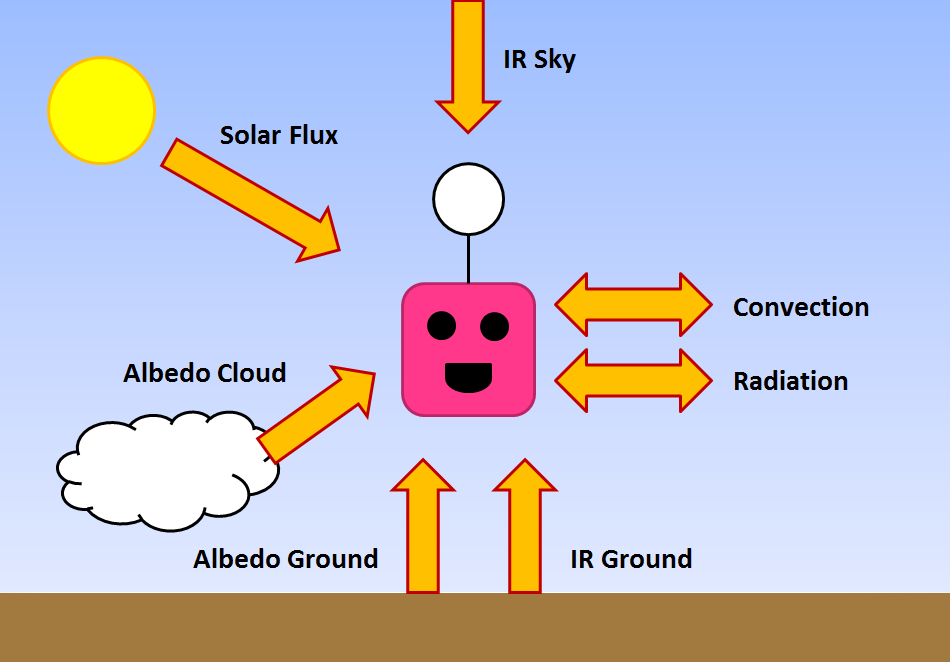
For each environmental condition you can replicate the follow conditions using the following:

•Air Temperature -60C to +40C:                   Dry Ice, Hair Dryer
•Pressure 0.01atm to 1atm:                             Refrigerator Pump
•Solar heat 180 W/m^2  –  340 W/m^2 :    Light Bulb, Heat lamp
•Winds/Forces up to 10g:                                Fan/Stairs (Ed Method)
•Humidity 0% – 100%:                                       Spray Bottle
The thermal/vac chambers design was then CAD’d:
envchamber3          chamdiagram
On the left is a vacuum pump connected to a schedule 40 PVC tee with 1/2″ thick polycarbonate lids sealed by silicone rubber. Outside you can see a light bulb facing the window which is used to replicate the expected solar flux. In the original design, a peltier cooler was interfaced with a copper rod running from the outside into the chamber was used to cool the HAB inside. Due to a large thermal gradient across the copper rod this cooling system was scraped. The new cooling system was not only cheaper, but more effective. The solution was to wrap a small flat piece of dry ice with cloth and tape it to one side of the hab then hang the hab from fishing string inside the chamber. This would result in one side of the HAB getting very cold (-40C or so). This however requires you to run the pump continuously since the dry ice sublimates creating CO2 gas.  If you were to turn on the light bulb, you would notice one side getting warmer while the sides in the shadows remain cold.
9617079873_5dc762b936_b
Dry Ice & cloth taped on one side…
9620308350_540a28dc1b_c
You can see the light bulb, chamber, and the HAB inside..
9514411346_04a4c998e6_b
I ran kaynar wire through the top plate and filled it with epoxy. Holds up under pressure!
GOODDATA_color

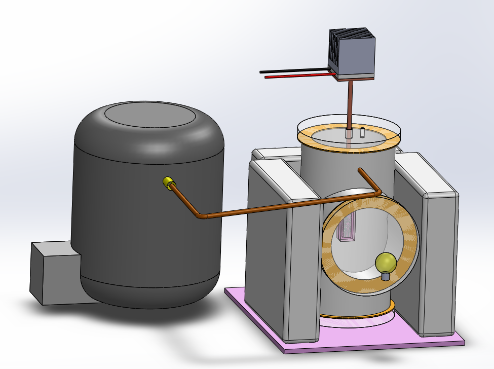
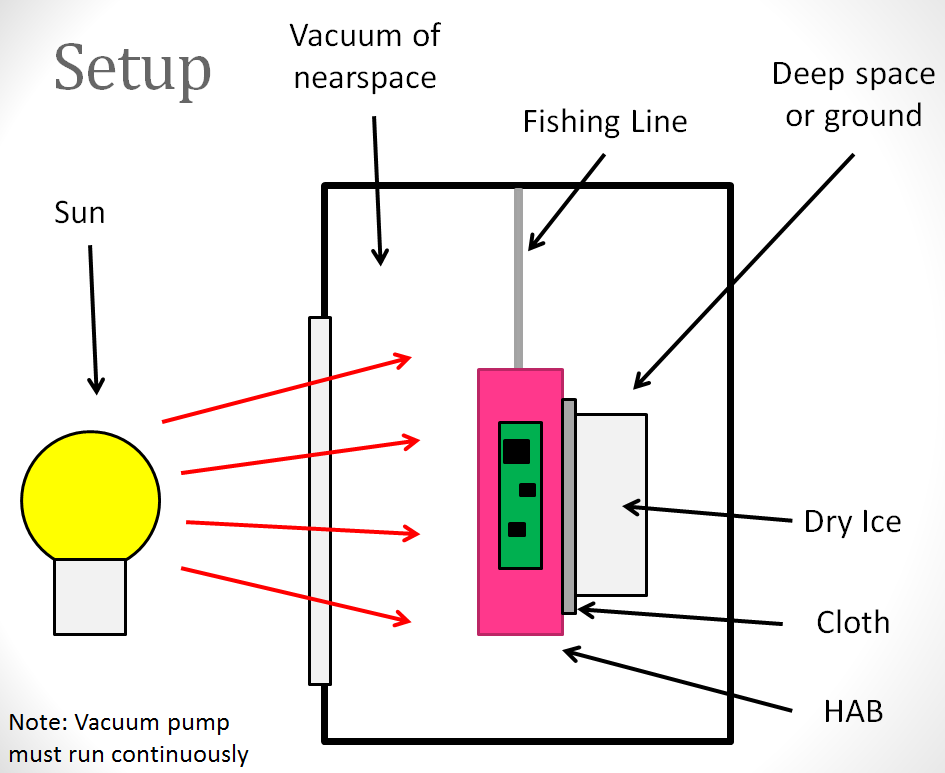
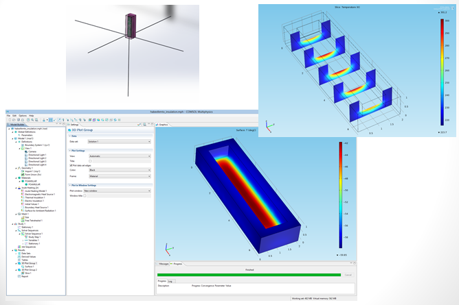
These were the results. The one side facing the “sun” got to about 28C (RED), while the cold side facing “deep space” aka dry ice got the outside of the insulation to about -40C (BLUE), and the inside of the HAB slowly moved down to about 10C (GREEN). Not bad, but not great. The problem with this setup is the fact that the dry ice is thermal interfaced with by conduction, rather than radiation. In a proper thermal vacuum chamber a shroud with liquid nitrogen tubes is run through the walls to produce cold walls. The walls are coated with a material such as black paint (high absorptivity), this forms good radiative thermal coupling. One could improve the design by having this and even placing it on a lazy susan to allow the hab to rotate and spin while the sunlight is applied. However, the setup would cost more than the original budget of “under $200”. Please note that this a “build at your own risk” project. I’m not responsible if your chamber implodes or hurts anyone. Also, do not cool down the PVC itself, that could make it very fragile.

Here’s the cost breakdown:

Environmental Test Chamber – Online & Easy    
Part Source Cost
4″ x 4″ x 4″ Schedule 40 PVC Tee http://www.homedepot.com/p/DURA-4-in-x-4-in-x-3-in-Schedule-40-PVC-REDUCING-Tee-SxSxS-401-422/203225320?MERCH=REC-_-product-6-_-203217750-_-203225320-_-N#.UhFTQpKxVjI $12.68
Extreme-Temperature Silicone Rubber http://www.mcmaster.com/#8632k42/=o4ghu7 $9.93
1/2″ thick, 6″ x 6″ http://www.mcmaster.com/#8560k274/=o4gi8k $25.38
Vacuum Pump – 2 Stage – 25micron http://www.amazon.com/Vacuum-Pump-2-Stage-Rotary-R410a/dp/B008BTM2N0/ref=sr_1_9?s=industrial&ie=UTF8&qid=1376867868&sr=1-9&keywords=Vacuum+Pump+2-Stage $87.00
Tubes/Connectors Hardware Store $40.00
Light Bulb & Fixture http://www.amazon.com/Zoo-Med-Economy-8-5-Inch-Chrome/dp/B0002DIWUU/ref=sr_1_1?s=industrial&ie=UTF8&qid=1376868265&sr=1-1&keywords=clamp+lamp+6in $15.73
Dry Ice Meat Market $5.00
Total Cost: $195.72
Environmental Test Chamber – Lower Cost
Part Source Cost
4″ x 4″ x 4″ Schedule 40 PVC Tee http://www.homedepot.com/p/DURA-4-in-x-4-in-x-3-in-Schedule-40-PVC-REDUCING-Tee-SxSxS-401-422/203225320?MERCH=REC-_-product-6-_-203217750-_-203225320-_-N#.UhFTQpKxVjI $12.68
Silicone Rubber Hardware Store $4.00
1/2″ thick, 6″ x 6″ http://www.mcmaster.com/#8560k274/=o4gtij $25.38
Fridge Pump Junk Yard/Craigslist $20.00
Tubes/Connectors Hardware Store $40.00
Light Bulb & Fixture http://www.amazon.com/Zoo-Med-Economy-8-5-Inch-Chrome/dp/B0002DIWUU/ref=sr_1_1?s=industrial&ie=UTF8&qid=1376868265&sr=1-1&keywords=clamp+lamp+6in $15.73
Dry Ice Meat Market $10.00
Total Cost: $127.79


In my talk I discuss the solutions to solving a hot or cold hab: http://arkorobotics.com/data/UKHAS_2013_arko.pptx


In my extended talk I also discuss solving software, radio/hardware configuration, and EMC (electromagnetic compatibility): http://arkorobotics.com/data/UKHAS_2013_EXTENDED_arko.pptx